 English
 한국어
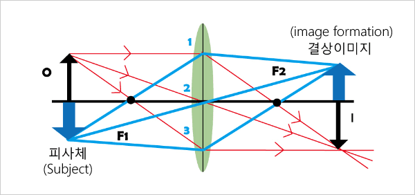
한국어- - Image formation refers to creating an image of an object through a lens.
- - In the figure above, it is shown that the light scattered from one point in the object spreads out to all directions, and then is gathered through the double lens back into one point to form an image.
- - This figure also shows that the light rays which are diverged from a point hit the lens at the same time, and then converge onto an imaging plane.
- - Like this, the light rays should be well separated and collected back together to create a good image. If some of the rays go beyond or do not reach the imaging plane, the image will be blurred because the light rays are not converged.
Basic Theory
홈 > 제품소개 > Automotive Solution
Lens Performance
The human eye’s vision and clarity are ultimately related to how well the lens contracts/relaxes. In cameras, this contraction/relaxation is usually fixed, which is related to lens alignment or performance.The center of distortion is also an important factor, especially for high-distortion cameras with high viewing angles.
 without distortion
 with distortion(Fish eye)
 BAD
BAD GOOD
GOOD
Luritech’s Lens Performance Inspection algorithm provides solutions for a variety of camera production environments, including camera distortion, extraction of Intrinsic parameter, and resolution inspection (SFR, Grid(TV).
Image Formation Principle
Focus Distance and (Subject/Focus)Depth
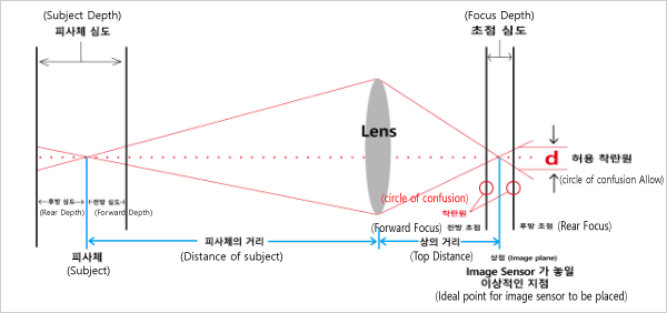
- - The light rays scattered from a point in the object converge into another point as they travel through the lens.
- - In the figure above, if object distance and lens location are fixed, the light rays would be collected onto the image plane.
- - With the image sensor placed on the image plane, a digital image for the camera screen can be created by letting each pixel on the sensor measure the brightness difference of the collected light rays.

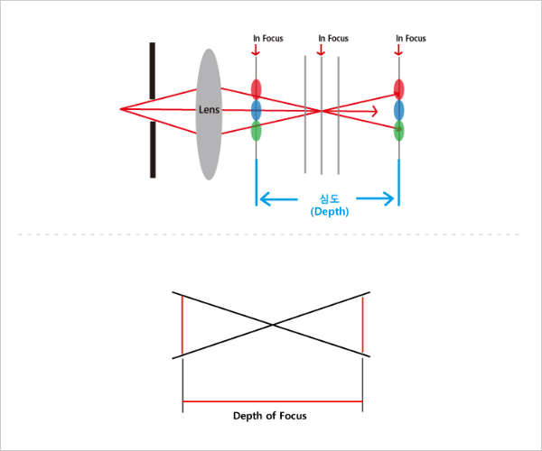
- 조리개(aperture)의 크기에 따라 심도가 변함
-
- - 작을수록 Beam이 Sharp해짐.
- - Beam이 Sharp할 수록 심도가 깊어짐.
- - The light rays scattered from a point are collected back into another point. And one point on the image sensor receives the collected rays. As shown on the left of the figure above, the blue-colored range where all of the scattered light rays can be collected is the depth of field and labeled as ‘In Focus.’
- - The images formed on the line labeled ‘Out Focus’ will be unclear and blurred because some rays land on green or red pixels when they are supposed to land on blue ones, and also because some different rays to land on green or red are mixed on blue.
- - Therefore, the range where the light rays from a point can be collected to a unique pixel of the sensor is the in-focus range, and called depth of focus.
- - On the right of the figure above, by reducing the aperture size, only the light rays coming to the center are passed and the light beams get sharper. Thus, the range where all the light rays can be converged through the same sized blue pixel will get wider.
- - A camera’s F-number is defined as the sharpness of the light beams converging through the lens, and can be obtained by a focal length(f) divided by an aperture diameter(D).
- - As the F-number gets bigger, the light beams get sharper and the depth of focus gets deeper, letting both far and near objects in focus. Conversely, as the F-number gets smaller, the in-focus range gets narrower.
Camera’s Resolving Power
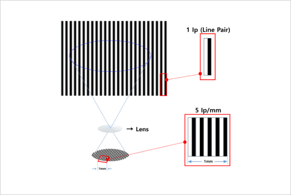
- - Lp/mm is mainly used in evaluating resolving power of a lens.
- - A resolving power of a lens is measured at the maximum spatial frequency at which black/white lines can be differentiated.
- - On the left, it is shown that there are 5 line pairs for every millimeter at the position of focal length.
- - In this case, 5 line pairs can be well differentiated, so this lens has at least 5 lp/mm of resolving power.
- - At a higher spatial frequency, the same differentiation might not be possible.
Lens Resolution Evaluation
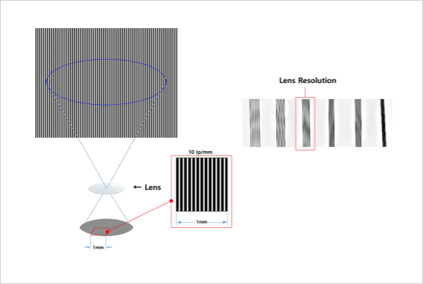
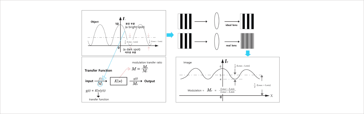
- - Modulation is a quantitative definition of the degree of resolution (black/white line differentiation).
- - A lens’ resolving power [lp/mm] is defined to be the number of line pairs per millimeter on the imaging plane at the maximum possible spatial frequency.
- - On the left, there are 10 line pairs per millimeter at a lens focal length.
- - In this case, the modulation value with 10 lp/mm is lower than the above one with 5 lp/mm.
Camera Resolution (MTF)
Camera Resolution (measurement method of EIAJ)
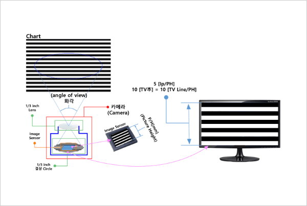
- - The resolution of the camera is expressed as the maximum number of lines pairs that can be divided and expressed in the camera output image.
- - In general, it is based on the maximum number of lines in the vertical direction.
→ PH(Picture Height) is the vertical height on the image sensor (unit: mm) - - The figure below shows 5 LP/PH (Line Pair/Picture Height) and 10 TV Lines.
- - [lp/PH] x 2 ↔ [LW/PH] ↔ TV 本 ↔ TV Line
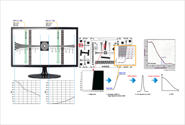
Camera Resolution (measurement method of SFR)
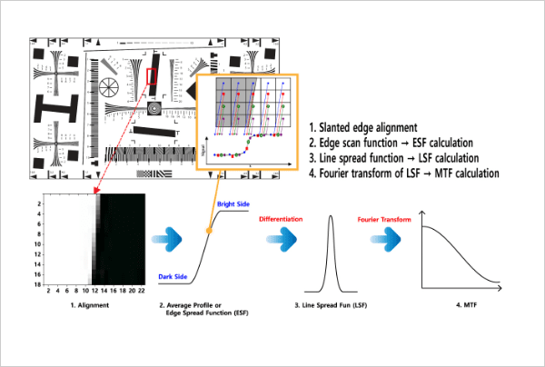
- - The MTF graph can be derived by analyzing brightness change characteristics from Slanted Edge.
- - In the MTF graph, C/P[Cycle/Pixel] of the set MTF value is obtained.
- - The camera resolution (maximum number of lines that can be expressed) is then obtained from the C/P.
- · [C/P] x number of vertical pixels on an image x 2 → TV 本(LW/PH)
Camera Resolution (measurement method of SFR) - Outline
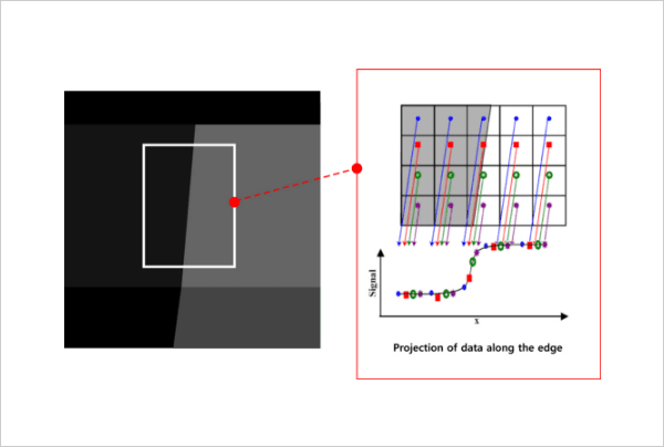
- - The image data shown in the left figure above of the slanted-edge part is converted into a straight line (graph) as shown in the right figure (ESF).
- - The resolution is evaluated by measuring (analyzing) the characteristics of the image change.
- - The higher the resolution, the sharper the brightness changes at the boundary.
- - The better the focus, the sharper the brightness changes at the border.
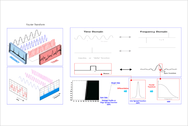
- - The MTF value is calculated by measuring the number of pixels required to go from the 10% point of the maximum brightness to the 90% point of that.
- - Since the actual data is read in pixel units from the image sensor, it is integerized.
- - difficult to find the locations of the 10% and 90% points.
- - Transformed into a continuous graph-type function through Fourier transform and mathematical transformation.
- - Resolution-related parameters like MTF 50% point, Nyquist point, and etc. are extracted from the converted continuous function.
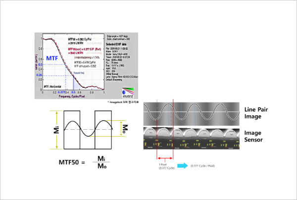
Camera Resolution (measurement method of SFR) - Slanted Edge method example
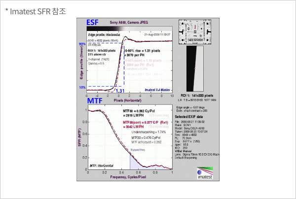
- ESF
-
- - Image 21% above the center of standard chart (ISO-12233)
- - It has a slope of Slanted Edge (about 5 degrees).
- - The size of the measurement area (ROI) is 141x333 pixels.
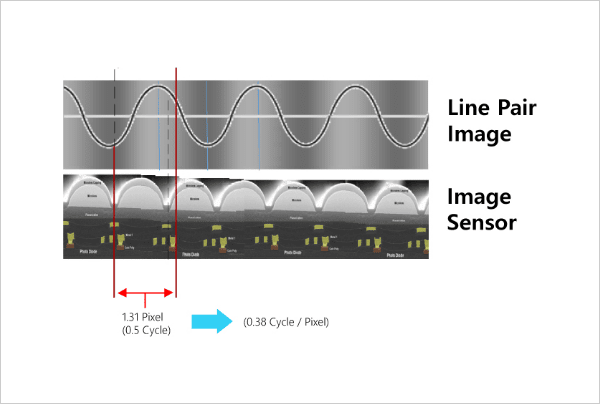
- - Pixel difference (edge rise distance) when brightness changes from 10% to 90%
- · The number of pixels required to invert the brightness once (0.5 Cycle) is 1.31
- · A total of 3070 TV Lines can be expressed by the image sensor (vertical). ( 4032/ 1.313355 Pixel = 3070 TV Line)
1) ESF
- - The Sync Function is obtained by modeling the Line Spread Function obtained from the Edge Spread Function using the Delta Function above and performing Fourier Transform.
- - Among these Sync Functions, from the center point of symmetry to the 1/d position is used as the MTF function. (d is the pulse width of Delta Function)
2) MTF
- - The X axis is Cycles/Pixel, the closer to 1, the higher the frequency signal.
· If more than one cycle fits in one pixel, the MTF gradually decreases. - - Limit frequency (NF: Nyquist frequency) of resolution
· NF is 0.5 C/P (Cycle/Pixel).
· In NF, MTF is 0.262 (26%).
· At frequencies above NF, aliasing occurs (difficult to identify patterns) - - In general MTF is applied as a criterion for sharpness when it is 50%.
· In the graph on the left, the MTF50 value is 0.377 C/P.
· In this case, the resolution is 3042 TV (TV Lien, LW/PH). (0.377[C/P] x 4032 [pixel] x 2 = 3040.128 LW/PH)
Camera Resolution (comparison for measurement method of SFR/EIAF)
- - From the EIAJ Chart Mark (gradual change in line width), obtain the MTF value for each position, and derive the MTF graph for each spatial frequency.
· Y-axis of graph: MTF value, X-axis: TV (LW/PH) - - In the MTF graph, the resolution of the set MTF value is obtained.
· Read the X value of the location. - - Camera TV value can be calculated from the specified resolution value.
- - MTF graph is found by analyzing brightness change characteristics from Slanted Edge.
- - In the MTF graph, C/P[Cycle/Pixel] of the set MTF value is obtained.
- - Camera resolution (maximum number of lines that can be expressed) is calculated from C/P.
· [C/P] x number vertical pixels on image x 2 → TV 本(LW/PH) - - Camera TV value can be calculated from the specified resolution value.
| Division | Camera resolution evaluation | Lens Evaluation | |
|---|---|---|---|
| SFR | EIAJ Chart | MTF | |
| Mark used |  |
 |
 |
| Measurement Parameter | Characteristics of change in Slanted Edge | MTF value per spatial frequency | MTF value per spatial frequency |
| Way to Obtain MTF Graph | Response characteristics of Delta Function(change in image brightness) per frequency | Difference between the Max. and Min. brightness per each spatial frequency | Difference between the Max. and Min. brightness per each spatial frequency |
| Evaluation Speed Property | ◎ | △ | △ |
| Criterion for Evaluation | MTF value | MTF value | MTF value |
| Main Unit | [Cycle / Pixel] x number of Pixel = [lp/PH] | TV Line | lp/mm |
| TV本 Conversion Equation | [lp/PH] x 2 TV本 | [TV Line] x 1 TV本 | X |
Camera Resolution (Unit Conversion Table of Resolution Evaluation) - Terms and Units
- - MTF(Modulation Transfer Function)
- - L/mm = Lines per millimeter
- - SFR(Spatial Frequency Response)
- - Cycles/mm = Cycles per millimeter
- - LW/PH = Line width per picture height = TV Line = TV本
- - Cycles/pixel = Cycles per pixel
- - LP/mm = Line pairs per millimeter
- - LP/PH = Line pairs per picture height
| LW/PH TV 本 (TV Line) |
LP/mm | L/mm | Cycles/mm | Cycles/pixel | LP/PH | |
|---|---|---|---|---|---|---|
| LW/PH | x 1 | / [2 x picture height] | / picture height | / [2 x picture height] | / [2 x # vert. pixel] | / 2.0 |
| LP/mm | x [2 x picture height] | x 1 | x 2.0 | x 1 | x pixel pitch | x [picture height] |
| L/mm | x picture height | x 0.5 | x 1 | x 0.5 | x [pixel pitch / 2] | x [picture height / 2] |
| Cycles/mm | x [2 x picture height] | x 1 | x 2.0 | x 1 | x pixel pitch | x [picture height |
| Cycles/pixel | x [2 x # vert. pixel] | / pixel pitch | x [2 / pixel pitch] | / pixel pitch | x 1 | x [# vert. pixel] |
| LP/PH | x 2.0 | / picture height | 2 / picture height | / picture height | / # vert. pixel | x1 |
Related Product
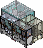 2D Calibration & Image test
 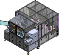 2D Calibration
 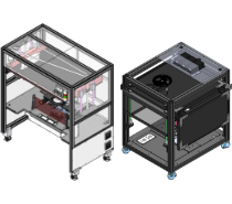 Lens Inspection
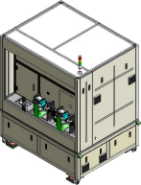 Image Test
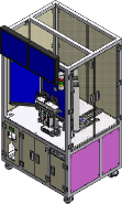 Distortion optical axis
- Business
 sales@luritech.com
  031-689-3696
